ADSL is a modem technology on the access network, which changes the existing infrastructure of the copper pair from the customer's house and the entire communications network, into a broadband network from end to end. ADSL enables, under optimum conditions, the transfer of multimedia, video, audio, high-speed Internet, by means of the existing access network up to a speed of 8 Mbps from the exchange to the subscriber, and up to 768 Kbps from the subscriber to the exchange (hence the name "asymmetric subscriber line").
The basic idea behind the technology is the need to transfer large amounts of information from the exchange to the subscriber's home (downloads of games, movies, etc.) while in the upstream channel (from the subscriber's home to the x exchange) a slower channel is sufficient, enabling communication with the content provider, sending emails or uploading to FTP servers.
ADSL technology uses the existing copper infrastructure deployed all over the country, making the broadband network possible without having to set up a new infrastructure. The technology enables maximum utilization of the typical bandwidth of the copper lines by means of complex data processing and encoding. Instead of using frequencies of 4 kHz, as was done until now, we use a range of frequencies between 0 KHz and 1.1 MHz, where standard ADSL system use 256 frequency channels (for the information moving downstream to from the exchange to the subscriber and for the upstream channel) with a bandwidth of 4 KHz per channel, thus enabling the transfer of much more information.
Technical Characteristics of ADSL
v Asymmetric distribution of the rate – up to 8 Mbps on the downstream channel and up to 768 on the u[stream channel.
v The range of frequencies is higher than the basic telephone frequency and up to a 1 MHz frequency.
v It is enabled on a regular analog telephone line or on an ISDN line.
v All the features of the line are maintained (such as conference call, call waiting, etc.).
v It is possible to surf the Internet and talk on the same line simultaneously (the use of filters does away with the need for a separate line for the Internet).
Sunday, September 13, 2009
Access Method Technology
Access Method
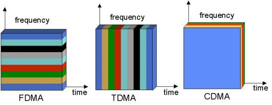
Technology plural access is method used to some information canals transmission at frequency band which have been determined. In general there are three kinds of accessing plural that is FDMA, TDMA, and CDMA.
FDMA (Frequency Division Multiple Access) Technique FDMA is technique access plural which generally used by cellular communication. Where delivered information signals through transmission media which is same to be differentiated frequency to signal every, that way between information one with other information can transmitted and accepted differentiated of frequency.

Spectrum RF for the technique of FDMA

Spectrum RF for the technique of TDMA
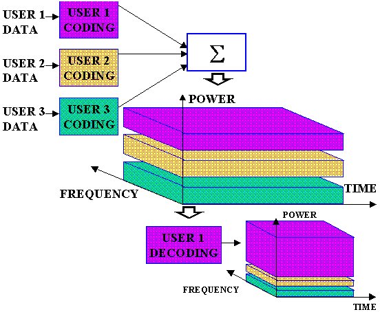
CDMA (Code Division Multiple Access) Technique CDMA is technique using code to differentiate between information which is one with other at same transmission channel, this technique not affect by transmission time and frequency, or this technique can some information transmitting with same frequency and during which at same time. So that limitation transmission media limited by bandwidth not make problems by using this technique.

Spectrum RF for the technique of CDMA
Basic concept of CDMA (Code Division Multiple Access) is communications system which use concept of cellular where cell is constrain for allocation used frequency and cell used constrain to determine customer constrain to service don’t customer which don’t service. Even problems the services amount or channels can overcome with system of multiplex just remain to there constrain use technique of multiplex, so that solution or constrain cell focus will not become effective again. Single way able to overcome this problem is improved performance of system multiplex. Temporarily this system of multiplex felt have some excesses by improving service capacities needn't again minimize physical of cell. Code Division Multiple Access (CDMA) is method access with user which a lot occupy one same cell areas and use same channel transfer of information (Communications). Usage of same channel have the meaning of every user same frequency and same during to communicated. Because using same frequency and during which at the same time between user, hence to differentiate user which is one with system the other CDMA use technique spread spectrum. Spectrum Spread is transmission technique by using code the method of spreading. That Code spreading is used as identification or can be conceived by address for every user which it uses same frequency and spanning same time also with the other user, so that receiver user will ear. Access plural is method used to some discussion channels frequency bands which have been determined.
Technology plural access is method used to some information canals transmission at frequency band which have been determined. In general there are three kinds of accessing plural that is FDMA, TDMA, and CDMA.
FDMA (Frequency Division Multiple Access) Technique FDMA is technique access plural which generally used by cellular communication. Where delivered information signals through transmission media which is same to be differentiated frequency to signal every, that way between information one with other information can transmitted and accepted differentiated of frequency.

Spectrum RF for the technique of FDMA
TDMA (Time Division Multiple Access) Technique TDMA is technique access plural where information occupying of same frequency channel and differentiated of transmission time. Become this technique will use difference of time between one information with other information in same frequency channel. Superior technique TDMA is bandwidth frequency compared to smaller used system of FDMA, but practically this technique still has limitation because speed of time used sampling will generate separate bandwidth.

Spectrum RF for the technique of TDMA
CDMA (Code Division Multiple Access) Technique CDMA is technique using code to differentiate between information which is one with other at same transmission channel, this technique not affect by transmission time and frequency, or this technique can some information transmitting with same frequency and during which at same time. So that limitation transmission media limited by bandwidth not make problems by using this technique.

Spectrum RF for the technique of CDMA
Basic concept of CDMA (Code Division Multiple Access) is communications system which use concept of cellular where cell is constrain for allocation used frequency and cell used constrain to determine customer constrain to service don’t customer which don’t service. Even problems the services amount or channels can overcome with system of multiplex just remain to there constrain use technique of multiplex, so that solution or constrain cell focus will not become effective again. Single way able to overcome this problem is improved performance of system multiplex. Temporarily this system of multiplex felt have some excesses by improving service capacities needn't again minimize physical of cell. Code Division Multiple Access (CDMA) is method access with user which a lot occupy one same cell areas and use same channel transfer of information (Communications). Usage of same channel have the meaning of every user same frequency and same during to communicated. Because using same frequency and during which at the same time between user, hence to differentiate user which is one with system the other CDMA use technique spread spectrum. Spectrum Spread is transmission technique by using code the method of spreading. That Code spreading is used as identification or can be conceived by address for every user which it uses same frequency and spanning same time also with the other user, so that receiver user will ear. Access plural is method used to some discussion channels frequency bands which have been determined.
Wireless Internet Service
One day customer services of the telecommunication operators received a call from a customer to complaint their data service. A customer said that they have lied to all their customers. Telecommunication operators promised to give us the best speed to their Wireless Internet Access through CDMA platform. But what customers get is not what they have been promising. Customer complaint since the Wireless Internet Access’ speed is very slow. Meanwhile another customer called to complaint with different cases. They have been trying so many times to connect data service of telecommunication operator but always failed. And finally they said that Wireless Internet Access offered by telecommunication operators is suck. It has more disadvantages rather than advantages.
I think whichever telecommunication operators that offer Wireless Internet Access CDMA, GPRS, 3G or EVDO will face the same cases; their will got a lot of complaint their customers. Some of customer’s complaint about the quality of speed, some about network availability and some about tariff that charged to them. Everyday we can see in the news paper regarding to this complaint. They releases a complaint to news paper due to after several complaint they have done to telecommunication operators, there is no improvement. They still face the same problem. Many customers disappointed to Wireless Internet Access offered by several telecommunication
Actually many factors are influence the quality of data service offered by telecommunication operators, CDMA, GPRS, 3G or EVDO. Data service more complicate than voice or SMS services. Many network elements are involved to have data service to their customers. Generally to have voice or SMS service, the network element that involved to these services are;
1. Customers’ handset/mobile phone
2. Base Transceiver Station (BTS)
3. Transmission link
4. Core Network (Mobile Switching Centre (MSC), Home Local Register HLR)
Meanwhile in data services, many others networks are needed in order to this service and as the result new additional network elements will influence the quality of service
In order to have data service (Wireless Internet Access), telecommunication operator must add several networks elements to existing network;
1. Modem to dial up or mobile phone with internet features
2. Internet link to Internet Service Provider (ISP)
3. Connection from telecommunication operators’ office to ISP
4. International connection from ISP to world wide
The problem of Wireless Internet Service could be from any side mentioned above and we need to analyze each complaint deeply to identify from which element the problem coming is and getting the best solution. It is totally different with SMS or voice service once the problems come. The problem could be from customers’ side but since customers did not know a lot about it, they do nothing in their side to resolve the problem. But mostly, the problem of Wireless Internet Service is coming from telecommunication operators’ end. And in some case, it is coming from their ISP partners.
CDMA Overview
ACCESS SCHEMES
For radio systems there are two resources, frequency and time. Division by frequency, so that each pair of communicators is allocated part of the spectrum for all of the time, results in Frequency Division Multiple Access (FDMA). Division by time, so that each pair of communicators is allocated all (or at least a large part) of the spectrum for part of the time results in Time Division Multiple Access (TDMA). In Code Division Multiple Access (CDMA), every communicator will be allocated the entire spectrum all of the time. CDMA uses codes to identify connections.
CODING
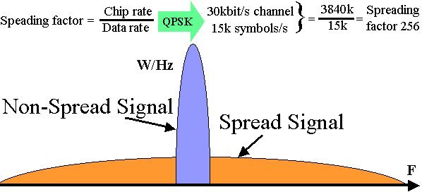
CDMA uses unique spreading codes to spread the baseband data before transmission. The signal is transmitted in a channel, which is below noise level. The receiver then uses a correlator to despread the wanted signal, which is passed through a narrow bandpass filter. Unwanted signals will not be despread and will not pass through the filter. Codes take the form of a carefully designed one/zero sequence produced at a much higher rate than that of the baseband data. The rate of a spreading code is referred to as chip rate rather than bit rate.
See coding process page for more details.
CODES
CDMA codes are not required to provide call security, but create a uniqueness to enable call identification. Codes should not correlate to other codes or time shifted version of itself. Spreading codes are noise like pseudo-random codes, channel codes are designed for maximum separation from each other and cell identification codes are balanced not to correlate to other codes of itself.
See codes page for more details.
THE SPREADING PROCESS
WCDMA uses Direct Sequence spreading, where spreading process is done by directly combining the baseband information to high chip rate binary code. The Spreading Factor is the ratio of the chips (UMTS = 3.84Mchips/s) to baseband information rate. Spreading factors vary from 4 to 512 in FDD UMTS. Spreading process gain can in expressed in dBs (Spreading factor 128 = 21dB gain).
See spreading page for more details.
POWER CONTROL
CDMA is interference limited multiple access system. Because all users transmit on the same frequency, internal interference generated by the system is the most significant factor in determining system capacity and call quality. The transmit power for each user must be reduced to limit interference, however, the power should be enough to maintain the required Eb/No (signal to noise ratio) for a satisfactory call quality. Maximum capacity is achieved when Eb/No of every user is at the minimum level needed for the acceptable channel performance. As the MS moves around, the RF environment continuously changes due to fast and slow fading, external interference, shadowing , and other factors. The aim of the dynamic power control is to limit transmitted power on both the links while maintaining link quality under all conditions. Additional advantages are longer mobile battery life and longer life span of BTS power amplifiers
See UMTS power control page for more details.
HANDOVER
Handover occurs when a call has to be passed from one cell to another as the user moves between cells. In a traditional "hard" handover, the connection to the current cell is broken, and then the connection to the new cell is made. This is known as a "break-before-make" handover. Since all cells in CDMA use the same frequency, it is possible to make the connection to the new cell before leaving the current cell. This is known as a "make-before-break" or "soft" handover. Soft handovers require less power, which reduces interference and increases capacity. Mobile can be connected to more that two BTS the handover. "Softer" handover is a special case of soft handover where the radio links that are added and removed belong to the same Node B.
See Handover page for more details.
MULTIPATH AND RAKE RECEIVERS
One of the main advantages of CDMA systems is the capability of using signals that arrive in the receivers with different time delays. This phenomenon is called multipath. FDMA and TDMA, which are narrow band systems, cannot discriminate between the multipath arrivals, and resort to equalization to mitigate the negative effects of multipath. Due to its wide bandwidth and rake receivers, CDMA uses the multipath signals and combines them to make an even stronger signal at the receivers. CDMA subscriber units use rake receivers. This is essentially a set of several receivers. One of the receivers (fingers) constantly searches for different multipaths and feeds the information to the other three fingers. Each finger then demodulates the signal corresponding to a strong multipath. The results are then combined together to make the signal stronger.
For radio systems there are two resources, frequency and time. Division by frequency, so that each pair of communicators is allocated part of the spectrum for all of the time, results in Frequency Division Multiple Access (FDMA). Division by time, so that each pair of communicators is allocated all (or at least a large part) of the spectrum for part of the time results in Time Division Multiple Access (TDMA). In Code Division Multiple Access (CDMA), every communicator will be allocated the entire spectrum all of the time. CDMA uses codes to identify connections.
 |
| Multiple Access Schemes |
CODING
CDMA uses unique spreading codes to spread the baseband data before transmission. The signal is transmitted in a channel, which is below noise level. The receiver then uses a correlator to despread the wanted signal, which is passed through a narrow bandpass filter. Unwanted signals will not be despread and will not pass through the filter. Codes take the form of a carefully designed one/zero sequence produced at a much higher rate than that of the baseband data. The rate of a spreading code is referred to as chip rate rather than bit rate.
See coding process page for more details.
 |
| CDMA spreading |
CODES
CDMA codes are not required to provide call security, but create a uniqueness to enable call identification. Codes should not correlate to other codes or time shifted version of itself. Spreading codes are noise like pseudo-random codes, channel codes are designed for maximum separation from each other and cell identification codes are balanced not to correlate to other codes of itself.
See codes page for more details.
 |
| Example OVSF codes, used in channel coding |
THE SPREADING PROCESS
WCDMA uses Direct Sequence spreading, where spreading process is done by directly combining the baseband information to high chip rate binary code. The Spreading Factor is the ratio of the chips (UMTS = 3.84Mchips/s) to baseband information rate. Spreading factors vary from 4 to 512 in FDD UMTS. Spreading process gain can in expressed in dBs (Spreading factor 128 = 21dB gain).
See spreading page for more details.
 |
| CDMA spreading |
POWER CONTROL
CDMA is interference limited multiple access system. Because all users transmit on the same frequency, internal interference generated by the system is the most significant factor in determining system capacity and call quality. The transmit power for each user must be reduced to limit interference, however, the power should be enough to maintain the required Eb/No (signal to noise ratio) for a satisfactory call quality. Maximum capacity is achieved when Eb/No of every user is at the minimum level needed for the acceptable channel performance. As the MS moves around, the RF environment continuously changes due to fast and slow fading, external interference, shadowing , and other factors. The aim of the dynamic power control is to limit transmitted power on both the links while maintaining link quality under all conditions. Additional advantages are longer mobile battery life and longer life span of BTS power amplifiers
See UMTS power control page for more details.
HANDOVER
Handover occurs when a call has to be passed from one cell to another as the user moves between cells. In a traditional "hard" handover, the connection to the current cell is broken, and then the connection to the new cell is made. This is known as a "break-before-make" handover. Since all cells in CDMA use the same frequency, it is possible to make the connection to the new cell before leaving the current cell. This is known as a "make-before-break" or "soft" handover. Soft handovers require less power, which reduces interference and increases capacity. Mobile can be connected to more that two BTS the handover. "Softer" handover is a special case of soft handover where the radio links that are added and removed belong to the same Node B.
See Handover page for more details.
 |
| CDMA soft handover |
MULTIPATH AND RAKE RECEIVERS
One of the main advantages of CDMA systems is the capability of using signals that arrive in the receivers with different time delays. This phenomenon is called multipath. FDMA and TDMA, which are narrow band systems, cannot discriminate between the multipath arrivals, and resort to equalization to mitigate the negative effects of multipath. Due to its wide bandwidth and rake receivers, CDMA uses the multipath signals and combines them to make an even stronger signal at the receivers. CDMA subscriber units use rake receivers. This is essentially a set of several receivers. One of the receivers (fingers) constantly searches for different multipaths and feeds the information to the other three fingers. Each finger then demodulates the signal corresponding to a strong multipath. The results are then combined together to make the signal stronger.
Overview UMTS
3G Systems are intended to provide a global mobility with wide range of services including telephony, paging, messaging, Internet and broadband data. International Telecommunication Union (ITU) started the process of defining the standard for third generation systems, referred to as International Mobile Telecommunications 2000 (IMT-2000). In Europe European Telecommunications Standards Institute (ETSI) was responsible of UMTS standardisation process. In 1998 Third Generation Partnership Project (3GPP) was formed to continue the technical specification work. 3GPP has five main UMTS standardisation areas: Radio Access Network, Core Network, Terminals, Services and System Aspects and GERAN.
3GPP Radio Access group is responsible of:
3GPP Core Network group is responsible of: 3GPP Terminal group is responsible of: 3GPP Services and System Aspects group is responsible of: Third Generation Partnership Project 2 (3GPP) was formed for technical development of cdma2000 technology which is a member of IMT-2000 family. In February 1992 World Radio Conference allocated frequencies for UMTS use. Frequencies 1885 - 2025 and 2110 - 2200 MHz were identified for IMT-2000 use. See the UMTS Frequency page for more details. All 3G standards are still under constant development. In 1999 ETSI Standardisation finished for UMTS Phase 1 (Release '99, version 3) and next release is due December 2001. UMTS History page has a list of all major 3G and UMTS milestones. Most of the European countries and some countries round the world have already issued UMTS licenses 2. UMTS Services UMTS offers teleservices (like speech or SMS) and bearer services, which provide the capability for information transfer between access points. It is possible to negotiate and renegotiate the characteristics of a bearer service at session or connection establishment and during ongoing session or connection. Both connection oriented and connectionless services are offered for Point-to-Point and Point-to-Multipoint communication. Bearer services have different QoS parameters for maximum transfer delay, delay variation and bit error rate. Offered data rate targets are: either by beauty contest or auctions. UMTS network services have different QoS classes for four types of traffic: UMTS will also have a Virtual Home Environment (VHE). It is a concept for personal service environment portability across network boundaries and between terminals. Personal service environment means that users are consistently presented with the same personalised features, User Interface customisation and services in whatever network or terminal, wherever the user may be located. UMTS also has improved network security and location based services. 3. UMTS Architecture A UMTS network consist of three interacting domains; Core Network (CN), UMTS Terrestrial Radio Access Network (UTRAN) and User Equipment (UE). The main function of the core network is to provide switching, routing and transit for user traffic. Core network also contains the databases and network management functions. The basic Core Network architecture for UMTS is based on GSM network with GPRS. All equipment has to be modified for UMTS operation and services. The UTRAN provides the air interface access method for User Equipment. Base Station is referred as Node-B and control equipment for Node-B's is called Radio Network Controller (RNC). UMTS system page has an example, how UMTS network could be build. It is necessary for a network to know the approximate location in order to be able to page user equipment. Here is the list of system areas from largest to smallest. 4. Core Network The Core Network is divided in circuit switched and packet switched domains. Some of the circuit switched elements are Mobile services Switching Centre (MSC), Visitor location register (VLR) and Gateway MSC. Packet switched elements are Serving GPRS Support Node (SGSN) and Gateway GPRS Support Node (GGSN). Some network elements, like EIR, HLR, VLR and AUC are shared by both domains. The Asynchronous Transfer Mode (ATM) is defined for UMTS core transmission. ATM Adaptation Layer type 2 (AAL2) handles circuit switched connection and packet connection protocol AAL5 is designed for data delivery. The architecture of the Core Network may change when new services and features are introduced. Number Portability DataBase (NPDB) will be used to enable user to change the network while keeping their old phone number. Gateway Location Register (GLR) may be used to optimise the subscriber handling between network boundaries. MSC, VLR and SGSN can merge to become a UMTS MSC. 5. Radio Access Wide band CDMA technology was selected to for UTRAN air interface. UMTS WCDMA is a Direct Sequence CDMA system where user data is multiplied with quasi-random bits derived from WCDMA Spreading codes. In UMTS, in addition to channelisation, Codes are used for synchronisation and scrambling. WCDMA has two basic modes of operation: Frequency Division Duplex (FDD) and Time Division Duplex (TDD). UTRAN interfaces are shown on UMTS Network page. The functions of Node-B are: The functions of RNC are: 6. User Equipment The UMTS standard does not restrict the functionality of the User Equipment in any way. Terminals work as an air interface counter part for Node-B and have many different types of identities. Most of these UMTS identity types are taken directly from GSM specifications. UMTS mobile station can operate in one of three modes of operation: UMTS IC card has same physical characteristics as GSM SIM card. It has several functions: |
Friday, September 4, 2009
Making New Connections Speedy
1. Click Start > All Programs > Accessories > Communications > Network Connections

2. Then click - New Connection Wizard

by TELKOM Speedy Marketing Division

2. Then click - New Connection Wizard

3. Window appears "New connection wizard", click Next
4. Select "Connect to the internet", click Next
5. Select "Setup my connection manually", click Next
6. Select "Connect using a broadband connection that requires a username and password", click Next
7. Fill ISP Name, Ex: speedy, click Next
8. Fill Username,password, and Confirm Password
Example:
Username: 111802100xxx@telkom.net
Password: xxxxxxxxxx
Confirm Password: xxxxxxxxxx
Click Next
9. Then klik checkbox "Add a shortcut to this connection to my dekstop", click Finish.
by TELKOM Speedy Marketing Division
Tuesday, September 1, 2009
ADSL, Configuration for Telkom Speedy

ADSL modem acts as Bridge
DSL (digital subscribe line asyncronus) as the primary tool to connect a PC to a home phone line (fixed phone / PSTN) to be connected to the Internet is increasingly recognized by many people.
Brands that are available in the market for this ADSL modem, including Prolink, Billion, Linksys, Aztec, and many more. But how to configure the ADSL modem we usually make as a mediator Point to Point Protocol over Ethernet (PPPoE) into a bridge.
Congenital Speedy ADSL modem by default, usually by Speedy advertiser your home or office acted as a mediator PPPoE. In fact, the role of an ADSL modem with PPPoE setting is less the maximum. If you want more than just according to the rules, it is necessary to play your ADSL modem is more than just a virtual protocol only.
We can change the ADSL modem which we use as a bridge. Role bridge here is like a 'private bridge' that connects your computer to the routing lengsung beginning of Speedy network. In addition, pengkonfigurasian ADSL modem as a bridge also gives us more advantages in overcoming the problems with dynamic ip is applied to Speedy.
Setting ADSL modem as a bridge, member We can control our internet access directly from a computer that we use without having to deal again with an ADSL modem. In other words, all you need with a direct Internet connection can we operate through operating system that we use. Here we will explain about how to configure your ADSL modem as a bridge.
The following examples use the Aztec brand ADSL modem.
* Open Internet Explorer. Way, click start-all programs-internet explorer
* In the browser URL box, type the address into your ADSL modem. Usually use the address 192.168.1.1 or 10.0.0.1
* Enter your username and password your ADSL modem. Then press the login button.
* Once in the main view mode, click on the setup options
* In the WAN menu, select the connection 0. Typically, the default configuration of an ADSL modem connection is put on setting connection 0.
* After the new display appears on the right, you can simply press the down arrow that is on the box type. Then select the bridge.
* On the bridge option encapsulation settings, select LLC.
* The PVC settings menu, fill in the VPI and VCI according to your region. Check this info on the Undernet. Configuring VPI and VCI for Surabaya and its surroundings, the value of the VPI: VCI = 0: 35
* On the choice of QoS (Quality of Service), select UBR.
* If the process is complete, click the button here apply.Di outlines your ADSL modem is acting as a bridge. You can see the outline of the configuration on the ADSL modem and applying it to the ADSL modem you use (other than the Aztec brand), because this step is a global step that can be applied to all the brands you change modem.Setelah your ADSL modem into a bridge, then the practical Your interner connection is lost.
For more mengoneksikan internet, here are steps you can do:
* Click Start - Settings - Control Panel - Network Connection.
* After that came the display of the Network Connection. Create a new connection by pressing the Create New Connection.
* After that will come a new look. At first view, press the Next button.
* After that, select Connect to the Internet, then press the Next button.
* After that, select the option Set up my connection manually. After that press the Next button.
* Next, select the option Connect using a Broadband connection that requires username and password. After that press the Next button.
* In the Connection Name, fill in the ISP Name box to your liking. Suppose you are content with Speedy_saya name. Then press Next.
* Next insert your username and password. This username and password in accordance with the username and password that you get from Telkom. If you could change your password, you must enter the password. After that, press the Next button.
* End the process by pressing the Finish button.
* After the login display will appear as when you first use telkomnet @ instant. Here, enter your username and password from your Speedy. Then press connect.
* If your username and password correctly, then your internet connection will go well. If not then the connection fails. Make sure you have entered your username and password with benar.Dari here, we have succeeded in changing our ADSL modem into bridge, and control of our Internet access directly from the Operating System that we use.
Good luck ..
Subscribe to:
Posts (Atom)